Special hydraulic chuck for long shafts, center-supported parts and alignment-sensitive workholding.
Ball-Joint / Ball-Lock Hydraulic Chuck
KORRETTO ball-joint / ball-lock hydraulic chuck is used for workpieces that require more than ordinary radial jaw clamping. It is suitable for long shafts, center-supported workpieces and special clamping setups where support, alignment and workpiece stability must be considered together. The product should be selected according to workpiece length, support method, clamping force, spindle interface and machining process.
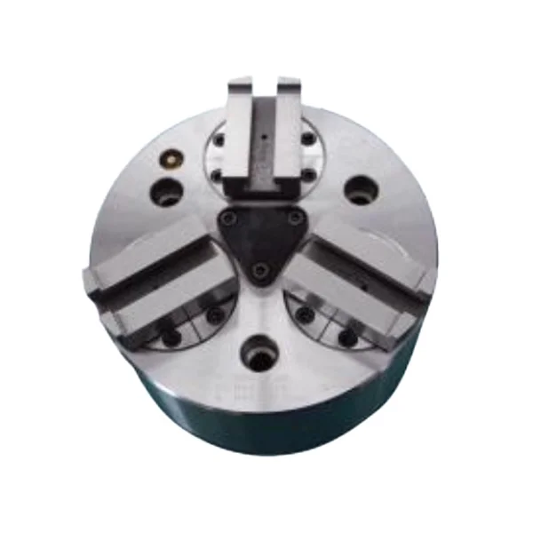
Product Overview
The ball-joint / ball-lock hydraulic chuck is a special hydraulic chuck for workpieces that need additional support or alignment consideration during clamping. It is not a general-purpose ball-lock component; it is a chuck structure used for specific CNC lathe workholding applications.
This page only covers the ball-joint / ball-lock hydraulic chuck. It does not replace standard hydraulic chucks or ordinary jaw chuck selection.
Key Features
| Feature | Description |
|---|---|
| Special support structure | Used where support and alignment are important to the clamping process. |
| Suitable for long workpieces | Helps address workholding problems on long shafts or center-supported parts. |
| Hydraulic chuck actuation | Works as a special hydraulic chuck within a CNC lathe setup. |
| Application-specific selection | Must be selected from the actual workpiece drawing and support method. |
| Not a general lock component | The product is a hydraulic chuck structure, not a separate locking hardware item. |
Typical Applications
- Long shaft workpieces
- Center-supported parts
- Alignment-sensitive CNC lathe workholding
- Special hydraulic chuck applications
- Workpieces requiring additional support during clamping
Technical Data and Dimensions
Use the drawing and parameter tables to check installation dimensions, spindle nose, allowable drawbar force, maximum clamping force, maximum speed, weight and matching machine conditions.
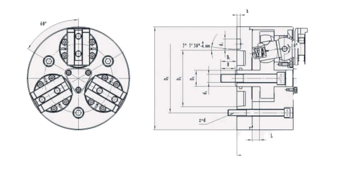
Use this drawing to confirm installation dimensions and technical parameters.
| Model | D | D1 | D2 | D3 | d1 | d2 | H1 | H | h1 | P | Q max | Q min | R max | R min | B | B max | B min | z-d |
|---|---|---|---|---|---|---|---|---|---|---|---|---|---|---|---|---|---|---|
| 160 | 160 | 82.563 | 104.8 | 30.16 | 16.3 | M16 | 85.3 | 104.6 | 6.5 | 24 | 73.15 | 22.2 | 20.3 | 30.8 | 28.5 | 42.7 | 31.5 | 3-M10 |
| 200 | 200 | 106.375 | 133.4 | 31.75 | 19.5 | M16 | 110 | 133 | 6.5 | 34 | 88.95 | 25.35 | 25.15 | 35 | 28.5 | 45.7 | 31.5 | 3-M12 |
| 250 | 254 | 139.719 | 171.4 | 41.27 | 24.2 | M20 | 119 | 148 | 8 | 44 | 112.7 | 30.3 | 35.7 | 45.5 | 35 | 57.5 | 38.5 | 3-M16 |
| 315 | 315 | 196.869 | 235 | 41.27 | 29.4 | M20 | 119 | 148 | 10 | 44 | 133.2 | 50.8 | 50.5 | 59 | 35 | 57.5 | 38.5 | 3-M20 |
| Model | Wedge Stroke (mm) | Jaw Stroke (Diameter, mm) | Allowable Push/Pull Force kN (kgf) | Max. Clamping Force kN (kgf) | Max. Speed (r/min) | Clamping Range (mm) | Matching Cylinder | Weight (kg) |
|---|---|---|---|---|---|---|---|---|
| 160 | 11.2 | 7.9 | 27 | 81 | 4000 | 12.7-120 | 100 | 18 |
| 200 | 14.2 | 9.5 | 36 | 108 | 3500 | 16-152 | 125 | 27 |
| 250 | 19 | 12.7 | 45 | 135 | 3000 | 50-203 | 125 | 45 |
| 250 | 19 | 12.7 | 45 | 162 | 2500 | 63-240 | 160 | 67.5 |
Selection Notes
- Confirm workpiece length, support method and clamping position.
- Check whether the part requires center support or special alignment control.
- Review spindle nose, drawbar force, jaw stroke and maximum speed.
- Check the machining process and cutting load.
- Do not select this chuck only by name; the workpiece drawing and support method must be reviewed.
FAQ
What is a ball-joint / ball-lock hydraulic chuck used for?
It is used for special hydraulic clamping applications, including long shafts, center-supported workpieces and parts that require support and alignment consideration.
Is this a general ball-lock component?
No. On this page, ball-joint / ball-lock refers to the hydraulic chuck structure used for specific workholding applications.
When should I choose this chuck?
Choose it when a standard hydraulic chuck cannot provide the required support, alignment or stability for the workpiece.
What should be checked before selection?
Check workpiece length, support method, spindle nose, drawbar force, clamping force, maximum speed, cutting load and machine conditions.
Can this replace a standard hydraulic chuck?
Not as a direct replacement. It is a special hydraulic chuck selected for specific workholding problems.